
OHD Anywhere® FAQs
1-Door Wireless Retrofit Kit FAQs | 3-Door Wired Retrofit Kit FAQs | Residential Garage Door Opener FAQs | App FAQs
1-Door Wireless Retrofit Kit FAQs
Compatibility
The 1-Door Wireless retrofit kit works with sectional, not one-piece garage doors.
| Compatible | Not Compatible |
| Sectional garage doors | One-piece garage doors |
The 1-door wireless retrofit kit works with most garage doors openers made after January 1, 1993.
| Brands | Protocols | |
| Genie, Overhead Door | Genie Intellicode 1 | |
| Genie Intellicode 2 | ||
| Genie 9 or 12 dipswitch binary | ||
| Overhead Door 9 dipswitch trinary | ||
| Chamberlain, LiftMaster, Craftsman, Raynor, Access Master, Steelcraft, Sears, Master Mechanic, Link, Garage Master, Garaga, AssureLink, True Value, Garage Access, Do It / Do it Best | Chamberlain Green – Billion Code | |
| Chamberlain Purple - Security+ | ||
| Chamberlain Red / Orange - Security+ | ||
| Chamberlain Yellow | ||
| Chamberlain Yellow – Security+ 2.0 | ||
| Chamberlain 9 dipswitch trinary | ||
| Sommer | Sommer | |
| Linear | Linear Megacode | |
| Wayne Dalton | Wayne Dalton | |
| Ryobi | Ryobi | |
| Guardian, Xtreme, Performax | Guardian | |
| FAAC | FAAC | |
| Stanley, Vemco, Multi-Code | Stanley 10 dipswitch binary |
Physical Installation Instructions
Bluetooth Set Up
The mobile phone is not connected to the hub. The problem may be on the mobile device side. If so, error messages are presented along with in-app help.
- Bluetooth is turned off in the phone settings - Go to settings and enable Bluetooth
- App does not have permission to use Bluetooth in the phone settings - Go to settings and then to the app, and turn on Bluetooth
- The phone is outside the range 30-50 ft range of Bluetooth. The range can be up to 150 ft if there are no obstructions. If the phone is far away from the hub, Bluetooth will not pair.
The problem could also be on hub.
- The hub is not in Bluetooth pairing mode. If the Wi-Fi LED is not blinking blue the hub is not in pairing mode. Be sure to press the Wi-Fi button until the hub beeps and you see a blinking blue Wi-Fi LED.
- The hub stays in pairing mode for 15 minutes. If the phone has not connected to the hub in 15 minutes, the process must be restarted.
- Verify that the hub is powered. Check that the power adapter is plugged in, and the USB-C connector is fully inserted into the hub and power adapter.
Bluetooth pairing mode will automatically turn off after 15 minutes, whether connected to the app or not.
1. Add a Device - Click on the + sign on the home screen, then select add a gate / door.
2. Device Selection – Select 1-door retrofit kit from the list
3. Physical Installation Instructions – follow the instructions to mount the hub and the door sensor. The door sensor must be mounted to the door to complete setup.
4. Setting Up the Hub - Press Wi-Fi button until the device beeps. The Wi-Fi LED will begin flashing blue, indicating that Bluetooth is in pairing mode.
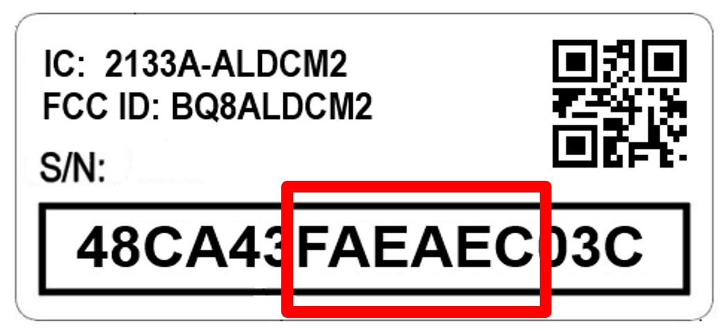
5. Connecting the Hub to the app via BT - The mobile application securely connects to the hub using Bluetooth. It is unlikely that more than one retrofit kit is in pairing mode at the same time, however, if the app detects more than one hub, the app will list the BT ID. The Bluetooth ID is eDCM87_XXXXXX, where XXXXXX is a 6-digit code from middle of serial number, digits 7-12. The label on the back of the hub and select the appropriate BT ID. If multiple devices show up, select your device from the list.
Device Registration
The serial number of every Wi-Fi product is established during manufacturing and sent to the cloud. This error occurs when someone registers a product serial number that is not on the list of manufactured devices. If you have received this error, contact customer service.
After the app receives the serial number, the app sends the serial number to the cloud to register the device. If the device is already registered to another owner, this error occurs.
Access can be given to other users by pressing the blue circle with the plus sign on the home screen and selecting virtual user.
If the product was acquired from another user, call customer service and provide evidence of ownership to correct this error.
Wi-Fi Set Up FAQs
If the device is already registered, you can use the following AP-mode process to configure Wi-Fi.
- Press and hold the Wi-Fi button on the hub until the Wi-Fi LED begins blinking blue, then changes to blinking blue and red. It should take about 10 seconds. When the lights are blinking blue and red, the hub is in access point mode.
- Go to the Wi-Fi settings on a smartphone or computer and connect the smartphone or computer Wi-Fi to the gdocntl-XXXXXX network.
- Next, go to the web browser on a smartphone or computer and enter 192.168.1.1. This connects your smartphone or computer to the hub’s embedded webpage.
- On the embedded webpage, click on the configure button and the embedded webpage to get to the set-up screen.
- Select a Wi-Fi network from a list of available networks and then scroll down, enter the password for the W-Fi network, and then select save. If your Wi-Fi network is not on the list, press the re-scan button to refresh the Wi-Fi network list or enter SSID manually.
- Device resets after saving credentials. The webpage will show ‘Configured’ “Saving...” before it resets.
- Once the hub is connected to the Wi-Fi network, the Wi-Fi LED will change status as the hub connects to the router and the cloud.
After the hub connects to the router, it tries to connect to the internet. This error occurs if the router is not connected to the internet, or a firewall prevents access to the internet.
- Check that the internet is available through the router. You can connect your phone to the router, turn off cellular, the verify that the phone can access the internet.
- If you have a firewall that is not blocking traffic or are unsure if the router is blocking access, connect to a Wi-Fi hotspot separate from the router.
To function effectively, your hub needs at least two bars or (-65dbm) of Wi-Fi signal to communicate with the app and the cloud. The easiest way to find out if you have adequate signal strength is
- Connect your smart phone to your Wi-Fi network
- With your phone in your hand, stand near the hub.
- Look at the Wi-Fi icon on the top of the screen on your smart phone. The Wi-Fi signal strength indicator is different than the cell signal indicator.
- Check that you have two bars of Wi-Fi signal strength.
After the app requests that the hub scan for Wi-Fi networks including SSID, security mode, and signal strength. The hub completes the Wi-Fi network scan and returns the results to the mobile app. The mobile app will list the networks in order of signal strength. Device will support WPA, WPA2 and WPA3.
If the Wi-Fi SSID is private, if the router is off, or if the signal is not reaching the hub, the Wi-Fi network will not appear on the list. Check that the Wi-Fi router is up, and that there is adequate Wi-Fi signal strength at the garage door opener.
You can also select to manually enter the network name in the app. If you are using a private network, you must manually enter the network name. When you enter the name, be sure that it is a 2.4 GHz network.
After registration is complete, the app starts the process to connect the hub.
- Get Network List – The app request that the hub scan for Wi-Fi networks including SSID, security mode, and signal strength. The hub completes the Wi-Fi network scan and returns the results to the mobile app. The mobile app will list the networks in order of signal strength. Device will support WPA, WPA2 and WPA3.
- Select SSID - Using the mobile app, select a Wi-Fi network from the list. If SSID is not on list, you can manually enter the SSID.
- Enter Wi-Fi Password - Enter the password and click the option to save the Wi-Fi password. If the password for the SSID has been saved, the saved password for that SSID is automatically filled in the next time you need it. The app, cloud, and device support the password standards based on encryption / security type (e.g., support 64-character passwords). You can cut and paste Wi-Fi passwords into the app.
- Hub Connects to Wi-Fi and Cloud - The hub connects to the Wi-Fi network, to the internet, and then to the cloud. The BT connection to the app reports status as does the Wi-Fi LED on the hub.
- solid green – connected to router, internet, cloud
- sold red – not connected to router
- blinking red – not connected to internet
- blinking green – not connected to the cloud
- Hub Terminates BT - BLE turns off when Wi-Fi has been successfully provisioned. BT pairing mode will automatically turn off after 15 minutes, whether connected to the app or not; or if provisioning mode is cancelled by a reboot.
If the app is disconnected from BT at any point after initial pairing, the app should notify you that the BT connection has dropped and then direct you to go back to the ‘Enter Bluetooth Pairing Mode’ screen to put the device back into BT pairing mode and continue setup.
Door Position Sensor Setup
The door sensor pairing is designed to be straight forward. The process for pairing after initial programming is the same as initial pairing.
The Door Sensor Did Not Pair’ error.
After 120 seconds, if the sensor is not paired to the hub, the BT pairing mode on the door sensor will be terminated and the BT pairing LED on the door sensor will turn off. The BT pairing LED on the hub will continue to blink blue indicating that the door sensor is not paired. The hub will stay in pairing mode for 15 min. The app will time out 90 seconds after you press the door sensor button, the door sensor LED starts blinking blue, and the hub has not reported that the sensor is paired. The timeout error will instruct you to press the door sensor button again to initiate BT pairing mode.
- Try again and check that both the BT LED on the hub is blinking blue and the LED on the door sensor is blinking blue. If the hub is not blinking blue, it may not be powered or may not be connected to the cloud or may not have received the command from the cloud to go into pairing mode.
- Check the hub is powered. Check that the power adapter is plugged in, and the USB-C connector is fully inserted into the hub and power adapter.
- Check the Wi-Fi LED status on the hub. If the Wi-Fi LED is not solid green the hub is not connected to the cloud.
Door Sensor Not Paired’ error
After the door sensor is paired and connected, if the door sensor is no longer paired and connected to the hub, the hub will report the BT status change to the cloud, and the cloud will update the app. The app will present an error and ask you to pair the door sensor.
The door sensor may become disconnected if the battery is low or dead, or if the sensor is moved away from the hub or the signal is blocked between the hub and door sensor.
To check the battery on the door sensor, press and release the door sensor button. If the door sensor LED starts blinking blue that indicates the battery level is good and the door sensor in BT pairing mode. If it does not blink blue the battery may be dead. Replace the battery then retry by pressing and releasing the door sensor button, when the door sensor is in range of the hub.
You can also view the battery level and the signal strength of the BT signal in the app by clicking on the door on the home screen to get the door detail screen, then select setup. The door sensor signal strength and battery level are shown.
The door position sensor should be mounted to the garage door end stile on the TOP door panel only. The end stile on the far left or right side of the door. The sensor must be attached to the door so that it moves up and down when the door moves up and down.
Clean the door where door position sensor will mount and install double sided tape to back of mounting bracket and affix the bracket to the door.
The app will direct you through the initial setup process. However, the door sensor can be reconnected without using the app after the initial connection.
- Hub in BT Pairing Mode – The hub will be put into BT pairing mode by the app set up flow and the BT pairing LED on the hub begins blinking blue, which indicates the hub is in BT pairing mode. When the hub is in BT pairing mode, the hub will report the BT status to the cloud, and the app status will be updated.
If the hub becomes disconnected from the door sensor after the pairing process is completed, the hub automatically scans and the BT LED will change to solid red, indicating that the hub is disconnected from the door sensor. - Sensor in BT Pairing Mode – If it is the first time you are setting up the sensor, pull the red tab on the door sensor and then press continue. On the door sensor, press and release the door sensor button, which is on the bottom half of the face of the door sensor. The BT pairing LED on the door sensor starts blinking blue, which indicates the door sensor in BT pairing mode.
- Sensor Pairs to the Hub - When both the hub and door sensor are in BT pairing mode, the door sensor will pair with the hub within 10 seconds. Pairing status will be sent to the cloud and updated in the app. The BT pairing LED on the hub will turn solid green and the BT pairing LED on the door sensor will turn solid green for 30 seconds.
- Name the Door - After the door sensor is paired, you can name the door. The door name change be changed via the app by going to the door detail screen, selecting the edit icon, and then clicking on the door name and typing in a new name.
Programming the Hub to Work with Your Garage Door Opener
- Problem with the Dip Switch Settings
Verify that the dip switch settings in the app match the garage door opener. Check the orientation of the dip switch. The text should be readable with 1 on the top and -1 or 0 on the bottom. The switches may be numbered from left to right as well. - Problem with the Door Sensor
If the door sensor shows closed, but the door is open, the door sensor may not be mounted to the door properly. Verify that the door sensor is mounted to the end stile on the top section of the door and that the brand information is right-side-up.
Check that BT LED is solid green, indicating that the hub is paired with the door sensor. - Problem with the Connection Between Device, App, and Cloud
The connection between the cloud and the device has dropped. Check the Wi-Fi LED status on the hub. If the Wi-Fi LED is blinking green the hub is connected to the internet, but not the cloud.
- Warning - Verify that the garage door is fully closed. If the door sensor shows the door is open, an error is presented. Hit “next,” acknowledging the warning.
- Operate Command Sent by Hub – Next the hub sends an operate packet to open the door. The door should open.
- Validate The Door Is Open - When the door sensor detects that the door is open, the configuration is complete. If the door sensor does not indicate the door is open, you are asked to check the door position. If the door is closed, you are asked to verify RF settings and retry. If the door is open, the learning process is complete.
The garage door must be closed at the start of the test. If the door sensor indicates the door is not closed, an error will be generated.
‘The Door Sensor Shows Open’ error
- Confirm that the garage door and that door is closed.
- Confirm that the door sensor is installed on the door. The sensor must be on the movable portion of the garage door and the brand on the sensor should not be upside down.
‘Programming Not Complete’ error.
If the hub does not report back a ‘Programming Not Complete’ error is shown.
- Problem with the learn mode on the garage door opener
- a) The learn mode timer on the garage door opener expired. Each garage door opener brand has a limited time that the opener stays in learn mode. If you take longer than 15-30 seconds between pressing the learn button and pressing the button in the app, letting the app know the learn button was pressed, the learn operation will not be successful. Retry.
- b) The learn mode timer on the garage door opener expired. Each garage door opener brand has a limited time that the opener stays in learn mode. If you take longer than 15-30 seconds between pressing the learn button and pressing the button in the app, letting the app know the learn button was pressed, the learn operation will not be successful. Retry.
- c) Learn button pressed twice or pressed again when in learn mode. Some brands do not remain in learn mode if the learn button is pressed again. Confirming the garage door matches the indication in the app when in learn mode.
- d) The garage door opener has exceeded the number of transmitters allowed. Each garage door opener limits the number of transmitters that can be programmed to the opener. If the opener is old, it is possible that some transmitters that are no longer in use are still stored in memory. Consumer the owner’s manual for your garage door opener to determine how to delete the saved transmitters and re-add them.
Problem with the hub installation
The hub is installed too close to the garage door opener. The hub should be mounted at least 5 feet away from the garage door opener to prevent distortion of the transmitter signal.
Problem with the Door Sensor
If the door sensor shows closed, but the door is open, the door sensor may not be mounted to the door properly. Verify that the door sensor is mounted to the end stile on the top section of the door and that the brand information is right-side-up.
Check that BT LED is solid green, indicating that the hub is paired with the door sensor.Problem with the Connection Between Device, App, and Cloud
The connection between the cloud and the device has dropped. Check the Wi-Fi LED status on the hub. If the Wi-Fi LED is blinking green the hub is connected to the internet, but not the cloud
Once the protocol is in the hub, the hub needs to be programmed into the garage door opener. The sequence for programming is different for different operator manufacturers.
- Warning - Verify that the garage door is fully closed. If the door sensor shows the door is open, an error is presented. The app warns you that the door is going to operate. Hit “next,” acknowledging the warning.
- Push Learn Button - Put the garage door opener into learn mode by pressing the learn button on the garage door opener.
- Validate The Door Is Open - When the door sensor detects that the door is open, the configuration is complete. If the door sensor does not indicate the door is open, the configuration fails, and you are asked to verify the door sensor is installed and brand information is correct, then retry.
- Select Brand – select the brand of their garage door opener from the list.
- Select Learn Button or Dip Switch – Look for the learn button on your garage door opener. If it is a Chamberlain product, note the learn button color. If you cannot find a learn button, check if your operator has dip switches. If your garage door operator is compatible, you will continue to set up.
- Set RF Protocol – Once the learn button or dip switch details are defined, the app sends the RF protocol to the cloud and cloud relays the protocol to the hub.
Compatibility Error
If you are unable to find a compatible brand with a learn button or dip switch, the app will link to a URL with a compatibility document that lists the compatible brands.
Cannot determine button color
Some of the Chamberlain button colors fade over time. Purple, red, and orange buttons fade and look brown. If your button is brown, try purple, then red.
‘Operator Type Not Set’ Error
This error occurs when the app does not receive confirmation from the cloud that the operator type is set. This can happen for the following reasons.
- The system was unable to complete the process. Verify the device is online, Wi-Fi LED is solid green. Verify the door sensor setup is complete, and the door sensor LED is solid green.
- The connection between the app and cloud is dropped. Log out and log back in to the app, which reestablishes the cloud and app connection, then restart the garage door programming setup process.
3-Door Wired Retrofit Kit FAQs
Compatibilty
The 3-Door Wired retrofit kit works with sectional garage doors, not one-piece doors.
| Compatible | Not Compatible |
| Sectional garage doors | One-piece garage doors |
The 3-Door Wired retrofit kit works with most garage doors openers manufactured after January 1, 1993.
| Compatible | Not Compatible |
| Genie Series II 1 | Made before January 1, 1993 |
| Overhead Door Series II 1 | |
| Genie Series III (needs adapter)2 | |
| Overhead Door Series III (needs adapter)2 | |
| Linear® – all models | |
| Marantec® – all models | |
| Stanley® – all models | |
| Wayne Dalton® – all models | |
| Chamberlain® pre-Security+ 2.0 models3 | Chamberlain® Security+ 2.0 models3 |
| LiftMaster® pre-Security+ 2.0 models3 | LiftMaster® Security+ 2.0 models3 |
| Craftsman® pre-Assurance+ 2.0 models3 | Craftsman® Assurance+ 2.0 models3 |
Notes:
- Series II openers are best identified by the wall console button(s) that are not black. This covers most Overhead Door openers, including all the currently sold models.
- Series III openers are best identified by the wall console button(s) that are black. If you have one of these units, you need a dry contact control adapter, part # 38013R, which are available at store.geniecompany.com.
- Chamberlain® or LiftMaster® or Craftsman® - If the antenna color is yellow or is identified as a Security+ 2.0 or Assurance+ 2.0 opener, then the 3-door wired retrofit kit is NOT compatible.
Physical Installation Instructions
3-Door Retrofit Kit Installation
Before you start wiring, make sure garage door opener is unplugged so the door does not operate unexpectedly. The door control module will wire directly to the garage door opener or directly to the wall control button.
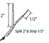
Wiring the door control module - Leaving the wire spool intact, split one end of the dual strand wire approximately 2 in. then strip 1/2 in. of insulation.
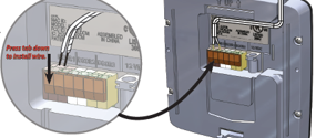
The retrofit kit will operate up to 3 garage door openers, so there are spaces to wire three doors on the wiring terminal on the back of the door control module, and each position corresponds to the buttons on the front of the panel.
Press down on the orange tab on the terminal strip for the appropriate door and insert the wire. Repeat the process for the second wire.
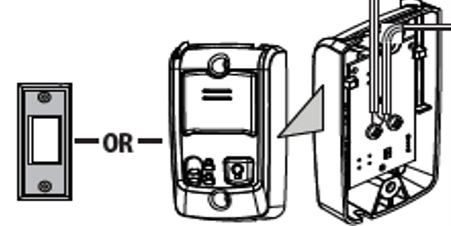
Wiring to the wall control push button – Remove the wall control push button from the wall and locate the screw terminals on the back. Connect the two wires to screw terminals along with existing wires. If there are no screw terminals or wiring connected to your wall control push button, it may be a wireless wall control, so you cannot use it and must connect directly to the garage door opener instead.
Wiring to the garage door opener – Garage door openers have terminal strips or screw terminals to connect to safety beams (STB or Beam) and to the wall control push button (PB). The wiring from the door control module connects with existing wires going to the wall control push button terminals.
If your garage door opener has screw terminals, connect one wire to the P.B. or push-button terminal and the other to the common or comm. terminal.
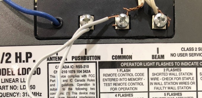
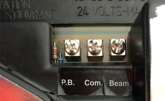
If your garage door opener has colored terminals, you can review the manual to confirm which terminal is for the push button or just trace the wire from the push button to the garage door opener. In the images below the push button is wired to the red and white terminals or R and W.
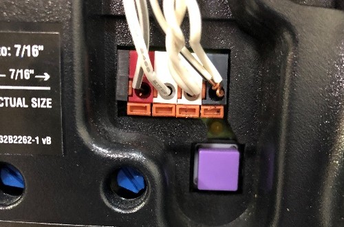
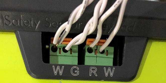
Sometimes the wall control push button is referred to as a basic wall control or BWC. Connect the wiring to the BWC terminals by pushing the orange clamp, removing the existing wiring, twisting the wires together, then inserting the twisted wires into the same terminal.
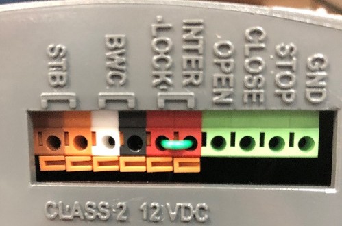
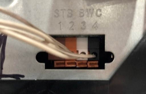
Before mounting the door control module, be sure to select a location that meets the following criteria.
- 5 ft from a power outlet - The door control module has a 5 ft power cord
- 25 ft from either the garage door opener or a wired wall control button - The control wire for that connects the door control module to either the garage door opener or a wired all button is 25 ft long.
- Where it can be seen and heard while standing in the garage - The door control module gives a safety warning when the door is being operated remotely so the warning must be seen or heard by anyone in the garage when the door is open.
The Door Control Module (DCM) is commonly mounted in the following locations.
- Mount above an outlet in the garage – If you mount the door control module next to an outlet, especially an outlet located near the personnel door, you can use the door control module as a second wall control button.
- Mount next to opener near ceiling - In this location you can plug it into the same outlet as the garage door opener and connect the control wire to operate the door from the door control module directly to the garage door opener.
Once mounting location has been determined, remove the mounting bracket from the back of the door control module, plug in the power cord to the power outlet and connect the plug to the door control module.
Scanning Serial Number
There are two reasons you might receive an error when attempting to register your device.
The serial number is invalid. The serial number must match an item on a list of valid serial numbers. If you are installing a retrofit kit, you must scan the serial number on the back of the retrofit kit, not the serial number on the garage door opener or other device. If you scanned the QR code on the back of the retrofit kit and are getting an error that the serial number is invalid, contact customer care.
Another user already owns the serial number. If you have already set up this device using another account, when you add it to a new account it will be deleted from the old account. An email is sent to the previous owner notifying them of the transfer. If they object to the transfer, you will need to contact customer care to resolve the problem. Similarly, if you moved into a new home and want to assume ownership of the device, scan the QR code to take ownership.
Wi-Fi Setup
Yes, there is a second approach to adding your Wi-Fi network and password passed to the door control module. You can connect a smartphone or computer to an embedded webpage in the door control module when it is in configuration mode. To use this method, press and hold the Wi-Fi button until the device beeps. When the LED changes from red to yellow, go to the Wi-Fi settings on your smartphone and connect to the gdocntl network. If you are using a computer, the computer must be connected to the gdocntl network.
Once you are connected to the gdocntl network, go to the web browser on a smartphone or computer and enter 192.168.1.1. This connects you to an embedded webpage in the door control module. Click on the configure button. The embedded webpage takes you to a set up screen. Select the home Wi-Fi network from a list of available networks, keep the WPA2 encryption selection, and then scroll down, enter the password for your home W-Fi network, keep the default service selection, and then select save. After hitting save, the first part of the configuration is complete, and the door control module connects to the home Wi-Fi network.
Once the door control module is connected to the home Wi-Fi network, the next step establishes a secure communication link between the door control module and the cloud. Press ‘connect’ to submit the configuration and complete Wi-Fi set up. The cloud and the door control module will exchange keys/tokens, so a secure communication link is established. The LED will change to solid green. If the LED is not solid green, the connection to the cloud was not successful. Contact customer care.
If the door control module LED turns red , the connection to the home Wi-Fi router was not successful. There are several reasons for this error.
- Wi-Fi coverage in your garage is insufficient
- The Wi-Fi network name and password were incorrect
- The manually entered Wi-Fi network name was the 5 GHz network not the 2.4 GHz network
- The network does not have WPA or WPA2 encryption.
Luckily, there are some ways you can resolve this issue yourself.
- Verify that you have two bars of Wi-Fi signal in your garage
- Verify that your Wi-Fi network and password are correct
- Make sure cellular data is turned off
- Check that the manually entered network name is a 2G not a 5G network.
If none of these solutions work for you, consider the alternative Wi-Fi configuration method, or contact the customer care team.
After you enter your Wi-Fi username and password, the door control module exits configuration mode and attempts to connect to the home Wi-Fi network and then to the cloud. As the device connects to your home Wi-Fi network, a series of confirmation messages will appear in the app indicating a successful Wi-Fi configuration and acknowledgement that setup is complete. A solid green light indicates that the door control module is properly connected and ready for use with the app. A flashing green light indicates that the door control module is connected to Wi-Fi router but has not established a secure communication link to the cloud. You should see a solid green light quickly, but it can take up to 5 minutes.
If the LED remains flashing green , the connection to home router is complete, but connection to the cloud is not established. The router may be blocking the messages to the cloud. Turn the power to your home Wi-Fi router off, wait 30 seconds, and then turn it back on. After the home Wi-Fi network is back up, repeat the Wi-Fi set up process in the app. If that does not work, you can also try the alternative approach to Wi-Fi set up. If you need assistance, please contact the customer care team.
During the Wi-Fi set up process, your smartphone needs to connect directly to the garage door Wi-Fi network. Some smartphones automatically try to use cellular data when a Wi-Fi network is not connected to the Internet. To be sure that the phone is connecting to the garage door network, turn off cellular data during setup.
For iOS devices, turn off cellular data by opening settings, then select “Cellular” to open Cellular settings. At the top of the page, tap to turn the green switch on the right-hand side of the screen off. The switch should turn grey.
For Android devices, turn off cellular data by swiping down from the top of the screen and tapping settings. Find and press ‘Data Usage’ to open cellular settings. Flick the ‘Mobile Data’ switch from on to off.
The yellow LED light on the door control module means that the opener is in Wi-Fi configuration mode. In configuration mode the door control module creates a Wi-Fi network that allows your phone to communicate with the garage door module. Once your smartphone is connected to the garage door network, named gdocntrl-xxxx, it allows your smart phone to pass your home Wi-Fi network name and password of your home Wi-Fi network to the door control module when you input it. Connecting to the gdocntl network is necessary to connect your door control module to your home Wi-Fi network.
A solid red light means that the unit is not connected to your home Wi-Fi network.
A solid yellow light means that the garage door module is in Wi-Fi configuration mode and ready to be configured. When the red LED changes to yellow, the door control module has created a gdocntrl-xxxx Wi-Fi network, which allows your smartphone to connect to the door control module.
A flashing yellow light means that the garage door module firmware is being updated.
A flashing green light means your device is communicating with your home Wi-Fi network but cannot access the internet or the cloud. Flashing green lights often change to solid green after 5 minutes, signaling your device has secured stable communication with your home Wi-Fi and the cloud. If the light remains flashing green after 5 minutes you may have ports on your Wi-Fi router that are blocking traffic between your device and the cloud
A solid green light means your device is successfully connected to your home Wi-Fi network and has established a secure communication link to the cloud.
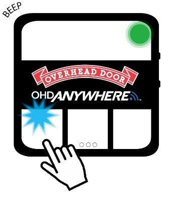
Double check that you are pressing the top button, labelled Wi-Fi. Press and hold the Wi-Fi button for several seconds until you hear a beep, and the LED light should turn yellow. If you do not hear the beep or the LED light does not turn yellow after several seconds, unplug the door control module, wait 30 seconds, then restore power. Press and hold the Wi-Fi button again. If you do not hear a beep or see the LED light turn yellow, contact the customer care team.
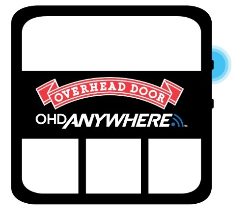
The Wi-Fi button is located on the upper right side of the door control module, and should be labled WI-FI. The diagram on the right also shows the precise location of the button by highlighting in it blue.
To function effectively, your door control module needs at least two bars or (-65dbm) of Wi-Fi signal to communicate with the app and the cloud. The easiest way to find out if you have adequate signal strength is
- Connect your smart phone to your home Wi-Fi network
- With your phone in your hand, stand near your door control module
- Look at the Wi-Fi icon on the top of the screen on your smart phone. The Wi-Fi signal strength indicator is different than the cell signal indicator.
- Check that you have two bars of Wi-Fi signal strength.
Door Position Sensor Setup
The door position sensor should be mounted to the garage door end stile on the TOP door panel only. The end stile on the far left or right side of the door. The sensor must be attached to the door so that it moves up and down when the door moves up and down.
Clean the door where door position sensor will mount and install double sided tape to back of mounting bracket and affix the bracket to the door. A video of the installation is available here.
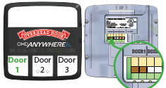
- Change the wiring - The wiring on the back of the door control module determines what button will operate the door. If you wire the garage door to door 2 in the back of the door control module, then you must connect the door sensor to the middle button to control door 2
- Delete the existing association of the door position sensor and the door button (see FAQ above)
- Manually pair the door position sensor to the door control module. (see FAQ above)
If the door position sensor is already paired with a door button, you can remove that association by pressing and hold the door position sensor button for approximately 7 seconds until the blue LED turns off. When the door position sensor button is pressed the blue LED should be on solid for approximately 7 seconds before going out. When the blue LED turns off the association of the door sensor to a door button is deleted.
When the door position sensor is no longer associated with the door button, the LED above the door button on the door control module turns red , indicating that the door position sensor has stopped communicating but is still associated with a door position sensor. Press and hold the door button on the door control module until you hear a beep and the blue LED above the door button begins to blink. Press the door button again and the blue LED goes off, indicating that the door button is no longer associated with the door position sensor.
Press and a hold down button on the door control module until you hear a beep. The light above the door button will begin flashing blue indicating that the door button is ready to be paired with a door position sensor.
If you do not hear a beep or the light above the button on the door control module does not begin flashing blue, unplug the door control module, wait 30 seconds, and then plug it back in and try again to press and hold the door button until you hear a beep.
While the LED above the door button is flashing blue, press and hold the button on the door position sensor until the blue LED begins slow flashing, about once per second, indicating that the door position sensor is ready to be paired with a door button.
If the blue LED on the door position sensor begins fast flashing, it is still associated with door button. Press the button on the door position sensor until the door position sensor LED stops fast flashing. It should take about 7 seconds, then try again to press the button on the door position sensor until it starts to slow flash.
If the blue LED on the door position sensor does not stop fast flashing after pressing and holding the door position sensor button, try pressing and holding the door position sensor button again until the fast flash stops.
If the blue LED on the door position sensor is off and never starts slow flashing, the battery may be dead. Check the battery by briefly pressing the door position sensor button. The blue LED on the door position sensor should illuminate while you are pressing the button. If the blue LED on the door position sensor does not turn on when you press the button, replace the battery on the door position sensor.
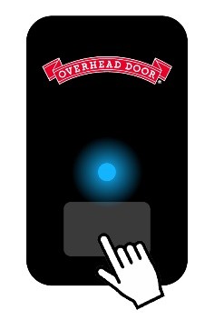
When the door position sensor connects to the door button the blue LED on the door position sensor will turn off.
A few seconds later the blue LED above door button 1 on the door control module is turned on solid indicating that door button 1 is associated with and communicating with the door position sensor.
If the LED light on the door control module is still flashing blue , press the door position sensor button a second time until it starts a slow blink, approximately once per second. This should pair the door position sensor resulting in a solid blue light on your door controller button.
If the blue LED on the door sensor is not flashing, press and hold the button on your door sensor until the blue LED begins slow flashing, about once per second.
If the blue LED does not flash when the button on the door sensor is pressed, the battery is likely dead. Open the battery compartment on the back of the door sensor to remove and replace the old battery with a new CR2450 coin cell battery.
The tab with the red arrow is located on the bottom of the device, under the battery compartment. Pulling the tab allows the battery to power up your door position sensor.
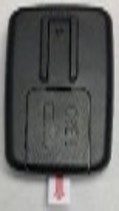
When you pull the activation tab on the door position sensor, the door sensor will automatically look for and pair with door button 1 on the door control module. The LED light on the door sensor will flash blue quickly indicating has already been associated with a door button is seeking to connect with that button on the door control module.
The blue LED on the door position sensor will turn off when it is connected to the door control module.
A few seconds later the blue LED above door button 1 on the door control module is turned on indicating that door button 1 is associated with and communicating with the door position sensor.
If the blue LED above door button 1 is not on, of if you want to associate the door position sensor to a different door button, you have to manually pair the door position sensor to the door control module. (see FAQ below)
The LED on the door position sensor can be slow flashing, fast flashing, on, and off. There are two colors, red and blue.
Solid red blue, - If you press door position sensor button momentarily, the LED will turn on and stay on while it is pressed. This was intended to be a quick way to check that the battery in the door position sensor is working. If the battery is ok, the LED will be solid blue. If the battery needs to be replaced, the LED will be solid red . If the battery is dead, the LED will not turn on.
Slow blue blink - If the door position sensor LED start flashing slowly, approximately once per second, the door position sensor is trying to connect to the door control module.
Fast blue blink - If the door position sensor LED starts flashing quickly it means that door position sensor is associated to a door button on the door control module, but it is not communicating.
Off - All of the door position sensor LED illuminations (on while button pressed, slow blink, or fast blink) are shown only for a limited time to conserve power consumption and extend battery life. The blue door position sensor LED remains off during normal operation and during setup after some time. For example, the door position sensor LED will blink fast or slow for a while, then the LED will turn off to save battery power, waking up every so often to see if it can reconnect to the door control module.
| Door Position Sensor Status | Door Position Sensor LED |
| When the door position sensor button is pressed briefly it performs a battery check | Blue – ok, Red – low Off – dead |
| Trying to pair with door control module | Blue slow blink |
| Trying to reconnect with door control module | Blue fast blink |
| Normal operation, during setup to save battery life | Off |
Each door has 2 status LEDs, one blue and one red.
Solid Blue - If a door position sensor has been associated with the door button and that door position sensor is communicating with the door control module, the blue LED is illuminated.
Solid Red - If a door position sensor has been associated with a door button and that door position sensor is NOT communicating with the door control module, the red door LED is illuminated.
Off - If a door position sensor is not associated with a button on the door control module, both the red and blue LED will be off.
Blinking Blue - There are two conditions that cause the blue LED to blink, one during operation and one during setup. During operation, the 5 seconds before the door move alert is completed you can abort the move by pressing any of the door buttons on the door control module. While an alert is being performed the blue LED for the door that is about move will blink. During setup, a blinking blue LED indicates that the door button is trying to pair with a door position sensor.
| Door Button LED | Red and Blue Off | Blue on Solid | Red on Solid | Blue Blinking (operation) | Blue Blinking (setup) |
| Button is associated with a door position sensor | No | Yes | Yes | Yes | No |
| The door position sensor is communicating with the door control module | - | Yes | No | Yes | No |
| Command received and 5 second warning | - | No | - | Yes | - |
| Door button is trying to pair with a door position sensor | Yes |
Door Position Sensor Operation FAQs
If you need to replace a door sensor, you will need to remove the association between the door button and the old sensor. Press and hold the door button on the door control module until you hear a beep and the blue LED above the door button begins to blink. Press the door button again and the blue LED goes off, indicating that the door button is no longer associated with the old door position sensor.
Now you can manually pair the new door position sensor to the door control module using the process here.
You can manually pair the door position sensor to the door control module using the process here.
If that does not work, follow the steps to delete an existing associated between a door button and door sensor in the door sensor here, then manually pair the door position sensor to the door control module.
When the battery dies on the door position sensor, it is no longer able to communicate with the door control module and the LED above the button on the door control module that is associated with the door position sensor will turn red .
When you replace the battery on the door position sensor, be sure that you are in the garage, so that the sensor can automatically reconnect to the door control module. When the light on the door control module changes from red to blue , the sensor is reconnected.
If the sensor did not automatically reconnect you can manually pair the door position sensor to the door control module. (see FAQ above)
When the battery is getting low, the sensor battery life indicator inside the app will change colors.
- Green: Battery has more than 40% life remaining
- Yellow: Battery has 40% life or less remaining
- Red: Battery has 20% or less life remaining
When the door position sensor battery dies, this message will appear on your smart device: “Paired But Not Connected”. Replace the existing CR2450 coin cell style battery.
You can also check the battery level on the door position sensor by momentarily pressing the button. If the battery is ok, the LED will be solid blue. If the battery needs to be replaced, the LED will be solid red. If the battery is dead, the LED will not turn on.
A red light means that the door sensor is paired with the door control module, but not communicating.
If you the battery on the door position sensor dies, the door control module will try to communiate with it but at after approximately 15 seconds, the door control module will turn on the red LED above the door button indicating that it has lost communicating with its paired door position sensor. The red LED will remain on if the door position sensor is not communicating or the door position sensor is no longer associated with the door button. To check the door position sensor battery, see FAQs below.
Replacing the battery in the door position sensor will cause the door position sensor LED to begin to flash rapidly and then automatically reconnect to the door control module without the need to press any buttons.
The door position sensor can also stop communicating after an extended power outage or if the door control module is unplugged. When the power on the door control module is off, the door sensor begins a fast flash and attempts to communicate, but when it fails, it pauses and then retries. Each time it fails, it waits longer to retry. If the power has been off for a long time, it could take up to 30 minutes for the door sensor to reconnect to the door control module. To reconnect the sensor faster, you can simply press the button on the door sensor and it will reconnect to the door control module.
Communication could also be disrupted if the path between the door position sensor and the door control module is obstructed. Check that that the door sensor is within line of sight and within 30 ft of the door control module and that they are not separated by a wall or other metal obstruction. In some cases, electrical interference may be preventing the door sensor from connecting to the door control module. Try turn off electronic devices such as LED lightbulbs located in or near the garage.
When the signal path is clear, the sensor should automatically reconnect to the door control module and the light should return to blue .
Communication can also be disrupted if you press and hold the door position sensor button for more than 5 seconds when the door position sensor is paired to a door button. In this case, the door position sensor stops communicating and the red LED above the door button on the door control module turns on.
To reestablish communication, press and hold the door button until it beeps the blue LED blinks and then press and hold the door position sensor button until it begins flashing. The sensor should automatically reconnect to the door control module and the light should return to solid blue .
Door Position Sensor App Error FAQs
Not Paired means that no door position sensor is connected to the door control module. If a door sensor was previosly connected, it could have been deleted from the door control module by pressing an holding a door button on the door control module until it beeps.
Follow the steps in the FAQs above for how to connect a door position sensor to reconnect the sensor.
Connection unknown means that the door position sensor has not been setup. The LED above the door buttons are off, indicating that the buttons are neither associated nor communicating with a door position sensor.
This can happen if a the door sensor has never been setup or if door button has been disassociated from a door position sensor by pressing and holding the door button on the door control module until it beeps and the blue LED above the door button begins to blink, then pressing the door button again and the blue LED goes off.
If the door sensor has never been setup, see FAQs above to setup the sensor.
If the door position sensor has been disassociated from the door button, see FAQs above to manually pair the door position sensor.
When the door position sensor is horizontal with the push button and logo facing down, the door position sensor reports the door is open. When the door position sensor is stood up vertically with the button on the bottom and the logo on the top, the door position sensor reports the door is closed.
If the door position sensor is in any other position it will report the door status as unknown. If the door status is unknown, the door will not be able to open or close, because the position is not known.
Make sure the door position sensor is mounted in the correct orientation and is located on the top panel of the garage door so that the sensor is vertical only when the door is fully closed.
Retrofit Kit Operation FAQs
Not Paired means that no door position sensor is connected to the door control module. If a door sensor was previosly connected, it could have been deleted from the door control module by pressing an holding a door button on the door control module until it beeps.
Follow the steps in the FAQs above for how to connect a door position sensor to reconnect the sensor.
Connection unknown means that the door position sensor has not been setup. The LED above the door buttons are off, indicating that the buttons are neither associated nor communicating with a door position sensor.
This can happen if a the door sensor has never been setup or if door button has been disassociated from a door position sensor by pressing and holding the door button on the door control module until it beeps and the blue LED above the door button begins to blink, then pressing the door button again and the blue LED goes off.
If the door sensor has never been setup, see FAQs above to setup the sensor.
If the door position sensor has been disassociated from the door button, see FAQs above to manually pair the door position sensor.
When the door position sensor is horizontal with the push button and logo facing down, the door position sensor reports the door is open. When the door position sensor is stood up vertically with the button on the bottom and the logo on the top, the door position sensor reports the door is closed.
If the door position sensor is in any other position it will report the door status as unknown. If the door status is unknown, the door will not be able to open or close, because the position is not known.
Make sure the door position sensor is mounted in the correct orientation and is located on the top panel of the garage door so that the sensor is vertical only when the door is fully closed.
Residential Garage Door Opener FAQs
Scanning Serial Number - Device Setup Faqs
There are two reasons you might receive an error when attempting to register your device.
The serial number is invalid. The serial number must match an item on a list of valid serial numbers. If you try to enter the garage door opener serial number instead of the iDCM serial number, you will get an error.
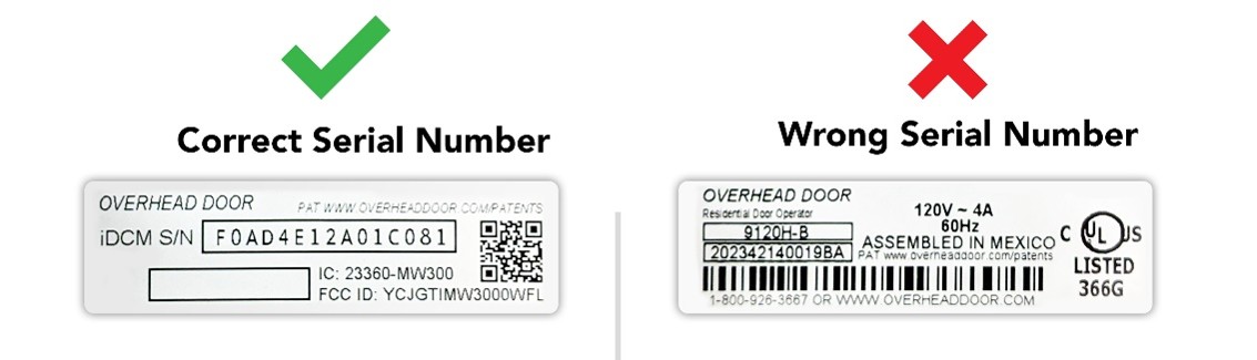
Another user already owns the serial number. If you have already set up this device using another account, you cannot add it to a new account until it is deleted from the old account. If you no longer have access to the old account, contact customer care and they can help you transfer ownership. Similarly, if you moved into a new home and want to assume ownership of the device, customer care can help.
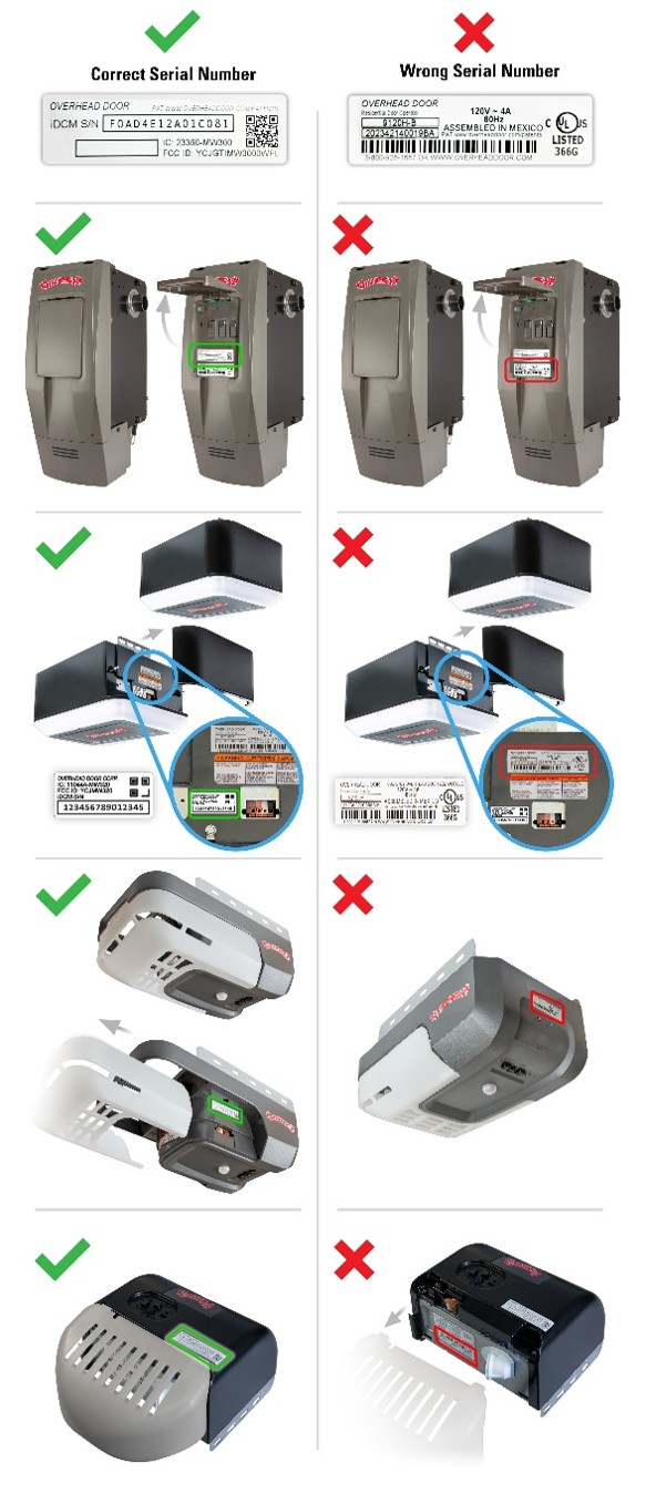
The serial number on a ceiling mount opener is on the bottom or the side of the device under the lamp cover on a white sticker. Look at the images below to find the location of the QR code on your model of garage door opener. It is preceded by iDCM S/N and has 15 characters in length. The QR code can be found immediately adjacent to the serial number.
Wi-Fi Set Up FAQs
Yes, there is a second approach to adding your Wi-Fi network and password passed to the garage door opener. You can connect a smartphone or computer to an embedded webpage in the garage door opener when it is in configuration mode. To use this method, press and hold the Wi-Fi button until the device beeps. When the LED changes from red to blue , go to the Wi-Fi settings on your smartphone and connect to the gdocntl network. If you are using a computer, the computer must be connected to the gdocntl network.
Once you are connected to the gdocntl network, go to the web browser on a smartphone or computer and enter 192.168.1.1. This connects you to an embedded webpage in the garage door opener. Click on the configure button. The embedded webpage takes you to a set up screen. Select the home Wi-Fi network from a list of available networks, keep the WPA2 encryption selection, and then scroll down, enter the password for your home W-Fi network, keep the default service selection, and then select save. After hitting save, the first part of the configuration is complete, and the garage door opener connects to the home Wi-Fi network.
Once the garage door opener is connected to the home Wi-Fi network, the next step establishes a secure communication link between the garage door opener and the cloud. Press ‘connect’ to submit the configuration and complete Wi-Fi set up. The cloud and the garage door opener will exchange keys/tokens, so a secure communication link is established. The LED will change to solid green. If the LED is not solid green , the connection to the cloud was not successful. Contact customer care.
If the garage door opener LED turns red, the connection to the home Wi-Fi router was not successful. There are several reasons for this error.
- Wi-Fi coverage in your garage is insufficient
- The Wi-Fi network name and password were incorrect
- The manually entered Wi-Fi network name was the 5 GHz network not the 2.4 GHz network
- The network does not have WPA or WPA2 encryption.
Luckily, there are some ways you can resolve this issue yourself.
- Verify that you have two bars of Wi-Fi signal in your garage
- Verify that your Wi-Fi network and password are correct
- Make sure cellular data is turned off
- Check that the manually entered network name is a 2G not a 5G network.
If none of these solutions work for you, consider the alternative Wi-Fi configuration method, or contact the customer care team.
After you enter your Wi-Fi username and password, the garage door opener exits configuration mode and attempts to connect to the home Wi-Fi network and then to the cloud. As the device connects to your home Wi-Fi network, a series of confirmation messages will appear in the app indicating a successful Wi-Fi configuration and acknowledgement that setup is complete. A solid green light indicates that the garage door opener is properly connected and ready for use with the app. A flashing green light indicates that the garage door opener is connected to Wi-Fi router but has not established a secure communication link to the cloud. You should see a solid green light quickly, but it can take up to 5 minutes.
If the LED remains flashing green , the connection to home router is complete, but connection to the cloud is not established. The router may be blocking the messages to the cloud. Turn the power to your home Wi-Fi router off, wait 30 seconds, and then turn it back on. After the home Wi-Fi network is back up, repeat the Wi-Fi set up process in the app. If that does not work, you can also try the alternative approach to Wi-Fi set up. If you need assistance, please contact the customer care team.
During the Wi-Fi set up process, your smartphone needs to connect directly to the garage door Wi-Fi network. Some smartphones automatically try to use cellular data when a Wi-Fi network is not connected to the Internet. To be sure that the phone is connecting to the garage door network, turn off cellular data during setup.
For iOS devices, turn off cellular data by exiting the app and opening settings. Once in settings, find the option labeled “Cellular” and tap to open Cellular settings. At the top of the page, tap to turn the green switch on the right-hand side of the screen off. The switch should turn grey.
For Android devices, turn off cellular data by swiping down from the top of the screen and tapping settings. Find and press ‘Data Usage’ to open cellular settings. Flick the ‘Mobile Data’ switch from on to off.
A red light means that the unit is not connected to your home Wi-Fi network.
A blue light means that the garage door is in Wi-Fi configuration mode and ready to be configured. When the red LED changes to blue, the garage door opener has created a gdocntrl-xxxx Wi-Fi network, which allows your smartphone to connect to the garage door opener.
A flashing green light means your device is communicating with your home Wi-Fi network but cannot access the internet or the cloud. Flashing green lights often change to solid green after 5 minutes, signaling your device has secured stable communication with your home Wi-Fi and the cloud.
A solid green light means your device is successfully connected to your home Wi-Fi network and has established a secure communication link to the cloud.
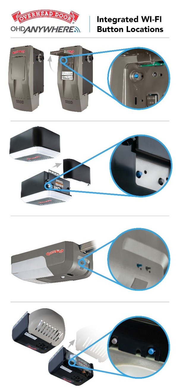
The LED light and blue button are located under the plastic light cover for most garage door openers. (See figure below). On some models, the button is on the front side or the bottom of the unit.
To function effectively, your garage door opener needs at least two bars or (-65dbm) of Wi-Fi signal to communicate with the app and the cloud. The easiest way to find out if you have adequate signal strength is
- Connect your smart phone to your home Wi-Fi network
- With your phone in your hand, stand in your garage where you are going to install the door control module.
- Look at the Wi-Fi icon on the top of the screen on your smart phone. The Wi-Fi signal strength indicator is different than the cell signal indicator.
- Check that you have two bars of Wi-Fi signal strength.
Wi-Fi Operation FAQs
When the device is showing offline, check to see that the Wi-Fi LED is solid green, which means that the device is connected to and communicating with the cloud systems. If the Wi-Fi LED is not solid green, click on the Configure Wi-Fi button in the offline error message or click on device setup on the door screen and then configure Wi-Fi.
If the device is showing offline, but Wi-Fi is connected and the Wi-Fi LED is solid green, refresh the data on the app by pulling down on the main screen, or call customer care for further assistance.
The device will show offline. You can click on the offline text to show an error message, and then click on configure Wi-Fi. You can also go to the door screen and click on device setup to find a configure Wi-Fi button.
Once you hit ‘configure Wi-Fi’ the app will take you through the steps to connect the device to your new router.
Sometimes, after a power outage, the garage door opener does not restart fully. Unplug the unit and if there is a battery backup, disconnect the battery, wait for 30 seconds, then restore power. The system should start up normally and lights return to their normal state.
Garage Door Operation FAQs
Remote operation is disabled when a safety interlock is not in place. Please check the following items:
- Verify the Bluetooth light fixture is installed and functional
- Verify the interlock circuit jumper is in place
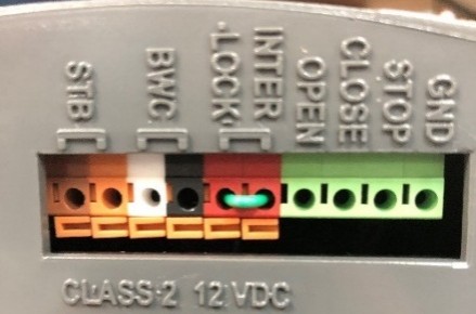
- Verify the photo eyes are powered and functional
App FAQs
Account Setup FAQs
If you cannot find the email to activate your account in your email, check your spam or junk folders. If you cannot find it there or if the activation time has expired, you can get another activation link by signing in with the credentials you used during sign-up. The activation link will only work on a mobile device if the app is already installed on that device.
If you are unable to click on the link in the email, it may be the security settings on the email app that blocks or disables links in the body of an email. You may have to update your email app to the latest version, change the security settings in your email app, or use another email app to access your email that allows you to click on links.
Be sure that your username is a valid email address that you can access and that your password has at least 8 characters, contains 1 uppercase, 1 lowercase, 1 number and 1 special character, and no spaces.
If you have already used the email address to set up an account, then you can skip the account signup set and simply login.
Account Sign-in FAQs
User - Virtual Key Setup FAQs
There are three major types of users – full access users, recurring users, and temporary users.
Full access users can control the door at any time unless/until the master account deletes the invitation. They can see if the door is open or closed but cannot add more users or create rules. Full Access can be given to people like family members or roommates.
Example: My daughter can have access to all doors.
Recurring users can operate the door on specific days of the week and/or during specific time windows. Recurring users cannot see the position of the door. The home page will provide an open and close option.
Example: The babysitter can have access to DOOR 1 every Monday and Wednesday between 8:00am – 4:00pm
Temporary users can operate the door for a preset length of time. If you select “temporary” as the access type, you will be able to set the length of the invitation. Recurring users cannot see the position of the door. The home page will provide an open option and a close option rather than reflecting the current position of the door.
Example: The plumber can have access to DOOR 1 on Monday, April 21st, 2019, between 8:00am – 10:00am
There are two types of accounts – an owner and a user account.
The owner controls access to the devices and can add additional garage door openers or garage door openers. Only owners can delete a device, create rules, invite users, and setup works-with partners.
A user account must be given permission to operate a device by a master account. Users can not invite others and can not create rules.
Rule Setup FAQs
There are two types of rules, a time-range rule and a duration rule.
A Time Range Rule sets a “schedule” for your garage door. For example, if DOOR 1 open between the hours of 11:00pm- 5:00am on any day of the week, perform an action.
A Duration Rule closes your garage door if it has been open for a certain period. For example, if DOOR 1 has been open for longer than 1 hour on either Monday, Wednesday or Friday, perform an action.
Actions can be ‘close’, ‘close and notify’ or ‘notify me’.
Notification Setup FAQs
Notifications depend on provider-specific message delivery services such as APNS (for iOS) and FCM (for Android) to deliver message to the end user device, and the delivery timing is controlled by those services. You can always confirm door events in the door history section of the app.
The notifications are customized by going to the main menu and selecting management notifications. Make sure notifications are enabled for the app in your smartphone settings.
There are several types of notifications.
- Door open and door closed notification give you an alert when the door status is changed from open or closed.
- System messages alert you if the device goes offline is in an error state.
- Door sensor battery notifications let you know if the door sensor on a retrofit kit has a low battery.
You can turn on and off notifications from the main menu by clicking manage notifications.
In addition, when you add users, you can set up notifications by user.
You can also create custom notifications using rules. For example, notify me if my door is open for more than an hour, or notify me if my door is open after 9pm.
Smart Home Setup FAQs
App Operation FAQs
There are many ways to operate the door. The door history in the app will tell you how the door was operated.
- By pressing the open/close button in the app
- By another user who you gave access
- By a rule that you set up in the app
- By a smart home or voice control system that you set up
- By a wall button or remote
Open your app, click on the door that experienced the problem to get to the door screen, then click on the door history tab. This shows you every operation for that door. Look up door history for the date/time and determine what operation occurred.
If the app indicates that it was opened by you using the app, and that you did not intend to operate the door, the app requires a push and hold operation on the door button to minimize your phone opening the door by mistake when the phone is in your pocket.
If the door history shows that another user operated the door, you may want to temporarily disable access to all other users on the main menu.
If the door history indicates that a rule operated the door, you can disable the rule by clicking on the door that experienced the problem to get to the door screen, then click on the rule tab, then turn off or delete the rules.
If the door history indicates that a smart home integration operated the door, you can disconnect the smart home system by removing the garage door from the smart home system.
If there is no operation in the door history log during the specified time period, then look at the log to see if the operation was offline during the specified time. If so, the door could have only been opened locally with a remote or the wall button during that time.
If the door history indicates that the door was operated using a wall button or remote and you are confident that you did not operate the door at that time, check the wiring on the wall control button and make sure that the wiring is not shorted.